
FPGA发端设计
接收机与FPGA
目录
作业要求
具体实现
发送的10101数据从txt文件中读取
- MATLAB仿真
1
2
3
4
5
6
7
8
9
10
11
12
13
data_len = 1024; %数据长度
data = randi([0 1],1,data_len);
fid = fopen('send_data.txt', 'w'); %创建txt文件
for i = 1:length(data)
if(i < length(data))
fprintf(fid,'%d\n',data(i));
else
fprintf(fid,'%d',data(i));
end
end
% fprintf(fid,'%d\n',sin_14bit);
fclose(fid);生成1024个0,1随机数,生成txt文件;
生成之后需要对发送序列进行映射,然后上采样,此处设计为4倍上采样1
2
3data = importdata('send_data.txt');
data_1 = (data'-1/2)*2;
data_up = upsample(data_1,4); - Verilog实现
读取txt文件在仿真文件中实现,映射及上采样代码在设计文件中实现
-
Design文件
核心代码
1
2
3
4
5
6
7
8
9
10
11
12
13
14
15
16
17
18
19
20
21
22
23
24
25
26
27//映射0变-1 + 4倍上采样
reg [1:0] data_map = 2'b00; //映射加插值后的信号
reg [1:0] cnt = 2'b00; //计数,4为一个周期
always @(posedge clk) begin
if (rst == 1'b1) begin
data_map <= 2'b00;
cnt <= 2'b00;
end
else begin
case(cnt)
2'b01:begin
if(data == 1'b1&&data_nd == 1'b1)begin
data_map <=2'b01;
cnt <= cnt + 2'b01;
end //data为1时不变
else if(data_nd == 1'b1) begin
data_map <= 2'b11;
cnt <= cnt +2'b01;
end //data为0时变为-1
end
default:begin
cnt <= cnt +2'b01;
data_map <= 2'b00;
end
endcase
end
end -
Testbench文件
1
2
3
4
5
6
7
8
9
10
11
12
13
14
15
16
17
18
19
20
21
22
23
24
25
26
27
28
29
30
31
32
33
34
35
36
37
38
39
40
41
42
43
44
45
46
47
48
49
50
51
52
53
54
55module tb_bpsk_send(
);
reg clk;
reg rst;
reg data = 1'b0;
initial begin
clk = 1'b0;
end
always #10 clk = ~clk; //50MHz clock
initial begin
rst = 1'b1;
#200
rst = 1'b0;
end
reg [1-1:0] data_mem [0:1023] ;//定义一个位宽为2bit,深度为1024的mem
initial begin
$readmemh("G:/vivado_project/bpsk/bpsk.srcs/sources_1/send_data.txt",data_mem);
end
integer i;
reg [1:0] counter = 2'd0;
reg data_nd = 1'b0;
always @(posedge clk) begin
if (rst|i==1023) begin
data <= 1'b0;
i <= 0;
counter <= 2'd0;
data_nd <= 1'b0;
end
else begin
case(counter)
2'd1:begin
data <= data_mem[i];
i <= i + 1;
counter <= counter + 2'd1;
data_nd <= 1'b1; //数据有效使能
end
default:begin
counter <= counter + 2'd1;
end
endcase
end
end
wire [23:0] s_up;
bpsk_send bpsk_send_m(
.clk(clk),
.rst(rst),
.data(data),
.data_nd(data_nd),
.s_up(s_up)
);
endmodule -
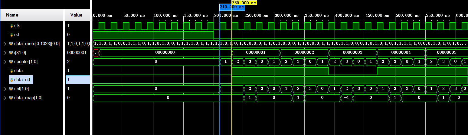
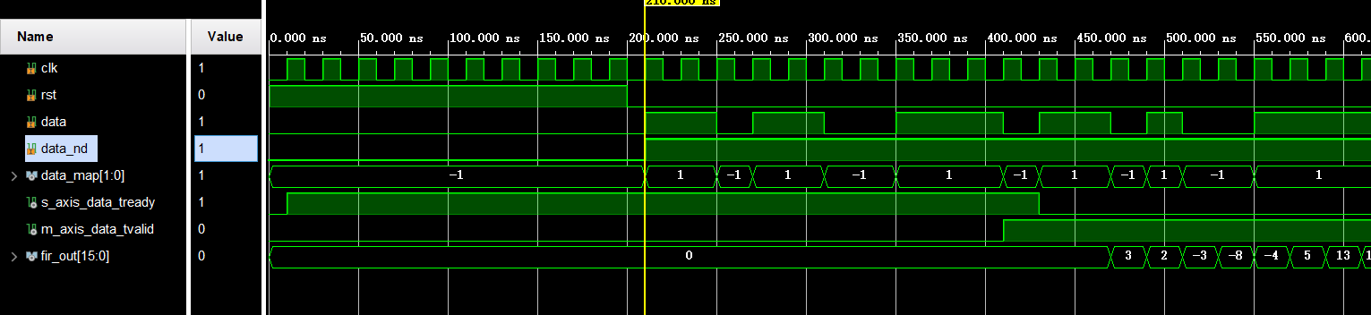
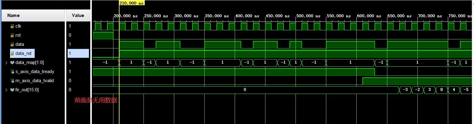
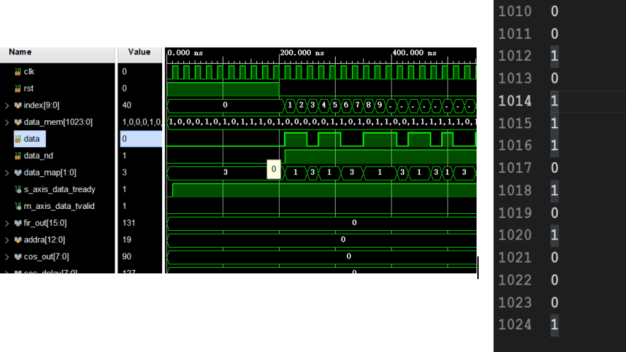
仿真波形
-
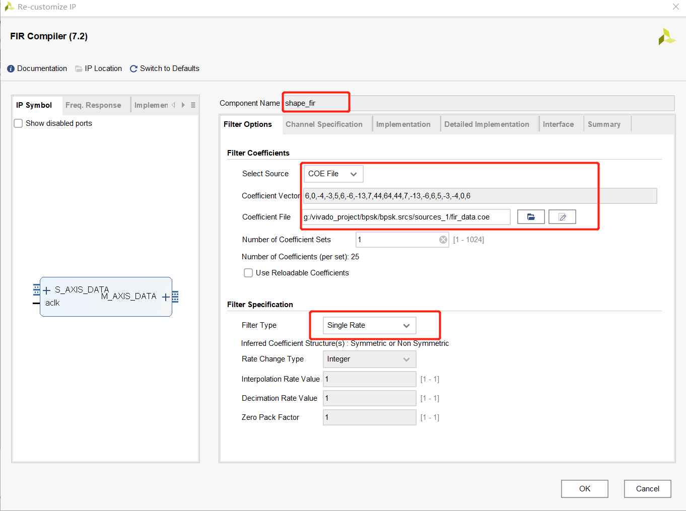
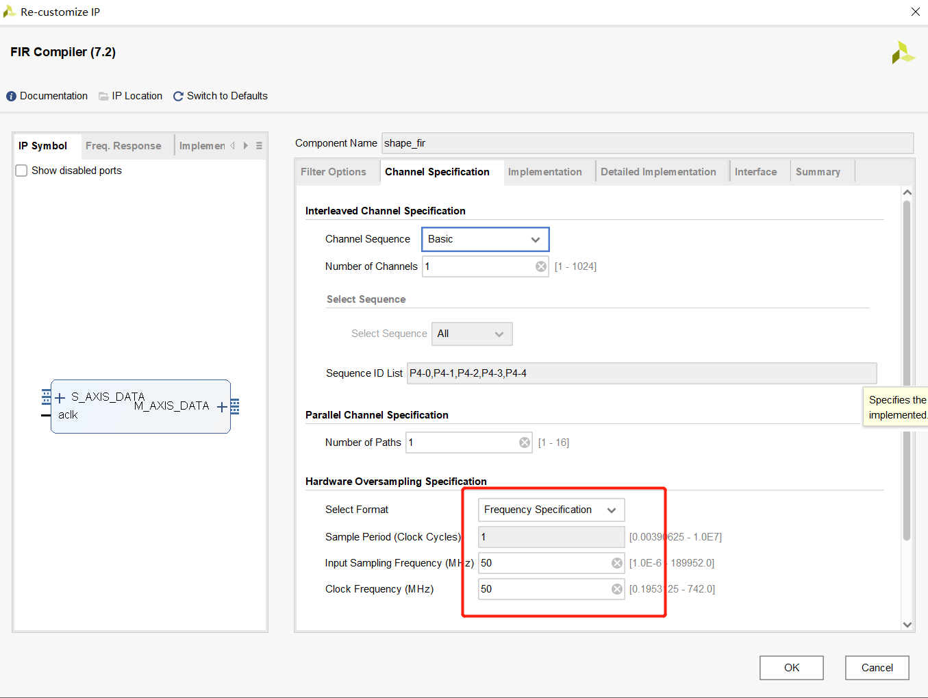
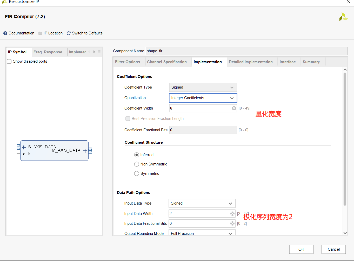
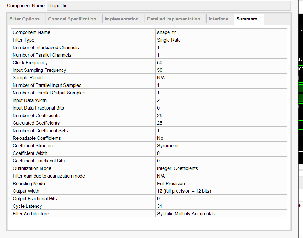
使用FIR核进行根升余弦
- Matlab
1
2
3
4
5
6
7
8
9
10
11
12
13
14
15
16
17
18
19
20
alfs = 0.35; % 滚降系数
osr = 4;
fir_rcos = rcosdesign(alfs,6,osr,"sqrt");
max_fir_rcos = max(abs(fir_rcos));
fir_rcos_bit = round((2^7-1)*fir_rcos/max_fir_rcos); %8bit量化
fid = fopen('fir_data.coe', 'w'); %创建COE文件
fprintf(fid, 'Radix=10;\n');
fprintf(fid, 'CoefData=\n');
for i = 1:length(fir_rcos_bit)
if(i < length(fir_rcos_bit))
fprintf(fid,'%d\n',fir_rcos_bit(i));
else
fprintf(fid,'%d',fir_rcos_bit(i));
end
end
% fprintf(fid,'%d\n',sin_14bit);
fclose(fid);
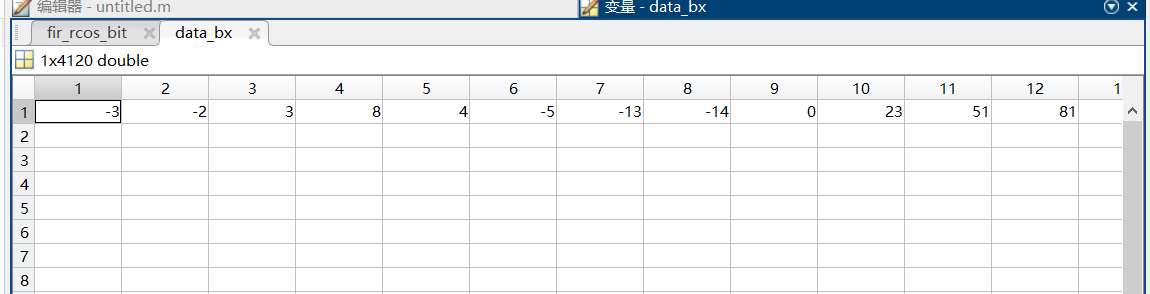
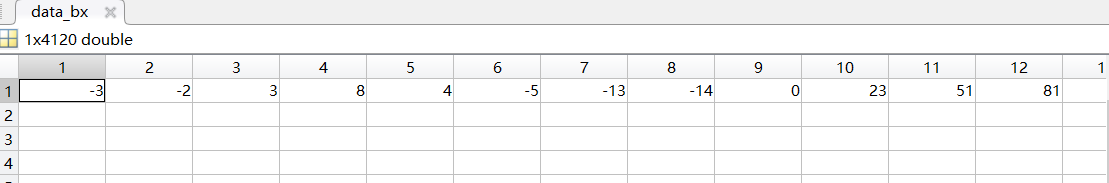
data_bx = conv(fir_rcos_bit,data_up); %通过滤波器 - verilog实现
-
Design
1
2
3
4
5
6
7
8
9
10
11
12
//根升余弦滤波FIR
wire s_axis_data_tready;
wire m_axis_data_tvalid;
wire [15:0] fir_out;
shape_fir shape_fir_m (
.aclk(clk), // input wire aclk
.s_axis_data_tvalid(1'b1), // input wire s_axis_data_tvalid
.s_axis_data_tready(s_axis_data_tready), // output wire s_axis_data_tready
.s_axis_data_tdata({6'b0,data_map}), // input wire [7 : 0] s_axis_data_tdata
.m_axis_data_tvalid(m_axis_data_tvalid), // output wire m_axis_data_tvalid
.m_axis_data_tdata(fir_out) // output wire [15 : 0] m_axis_data_tdata
); -
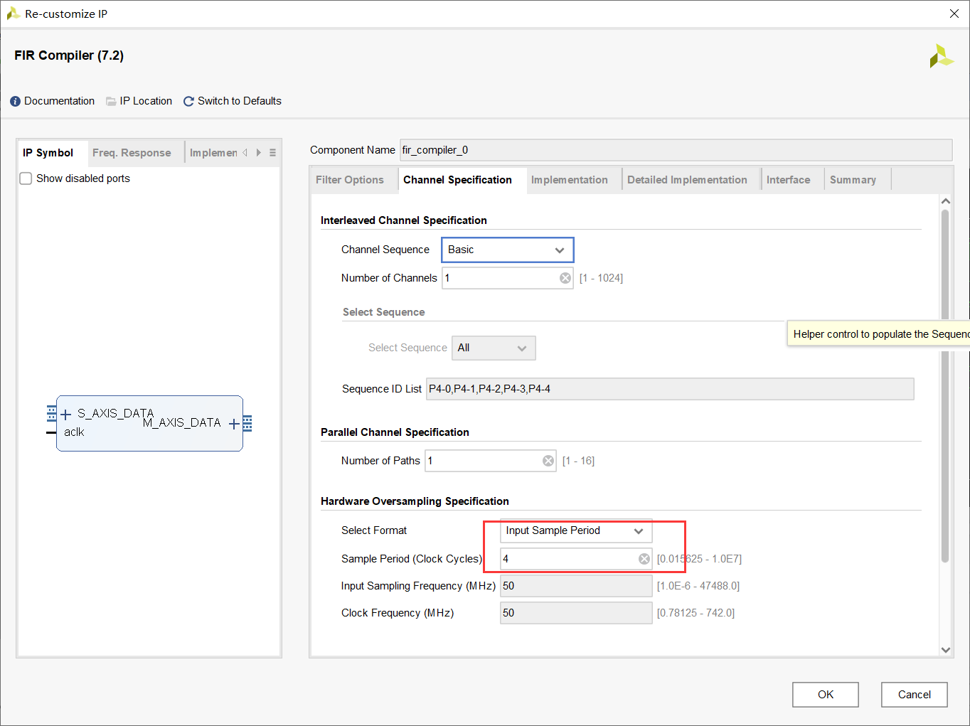
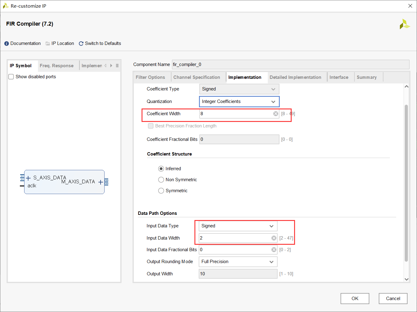
IP核设置
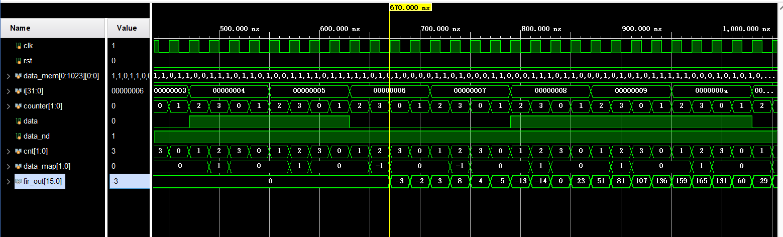
仿真通道文件和之前一样,为了检查错误,加了一个计数器用于检测
1
2
3
4
5
6
7
8
9
10
//用于观察的计数器
reg [32:0] cnt_1 = 33'd0;
always @(posedge clk) begin
if(rst)begin
cnt_1 <= 33'd0;
end
else begin
cnt_1 <= cnt_1 + 33'd1;
end
end -
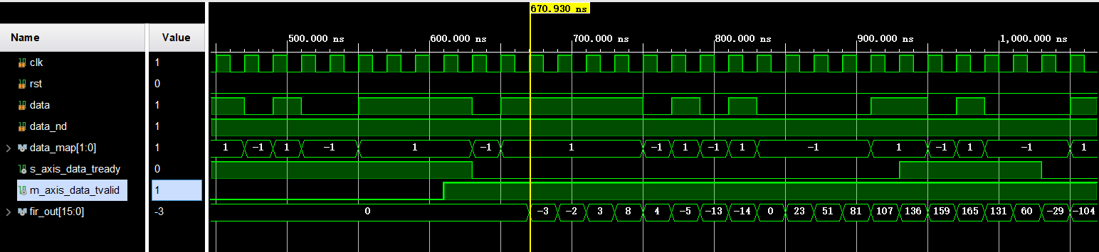
仿真输出
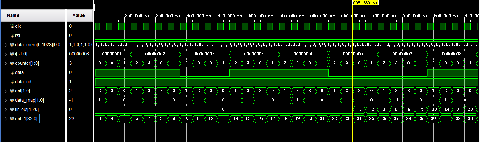
-
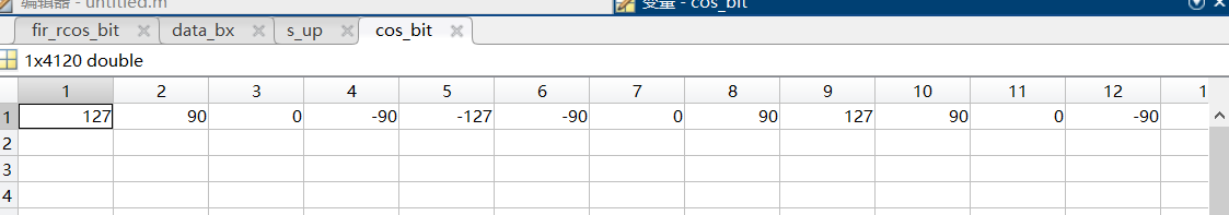
采用DDS生成中频载波
- MATLAB
生成载波序列,并对其量化,产生coe文件
1
2
3
4
5
6
7
8
9
10
11
12
13
14
15
16
17
18
19
20
fs = 16000; % 采样率
fc = 2000; % 载波频率
t = 0:length(data_bx)-1;
carrier = cos(2*pi*fc/fs*t); %载波
cos_bit = round((2^7-1)*carrier/max(abs(carrier)));%8bit量化
fid = fopen('cos_bit.coe', 'w'); %创建COE文件
fprintf(fid, 'memory_initialization_radix=10;\n');
fprintf(fid, 'memory_initialization_vector=\n');
for i = 1:length(cos_bit)
if(i < length(cos_bit))
fprintf(fid,'%d\n',cos_bit(i));
else
fprintf(fid,'%d',cos_bit(i));
end
end
% fprintf(fid,'%d\n',cos_bit);
fclose(fid);
plot(cos_bit); - verilog
-
design
1
2
3
4
5
6
7
8
9
10
11
12
13
14
15
16
17
18
19
20
21
22
23
24
//DDS生成中频载波
reg [12:0] addra;
wire [7:0] cos_out;
reg [7:0] cook;
parameter add_M = 1;
always @(posedge clk) begin
if (rst|addra==13'd4119) begin
addra <= 13'd0;
cook <= 8'd0;
end
else if(cook==8'd22) begin
addra <= addra + add_M;
end
else begin
addra <= addra;
cook <= cook + 8'd1;
end
end
cos_local cos_local_m (
.clka(clk), // input wire clka
.ena(1'b1), // input wire ena
.addra(addra), // input wire [12 : 0] addra
.douta(cos_out) // output wire [7 : 0] douta
); -
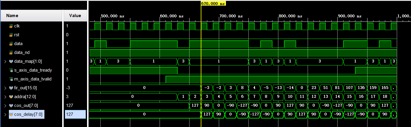
仿真输出
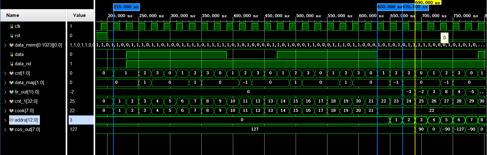
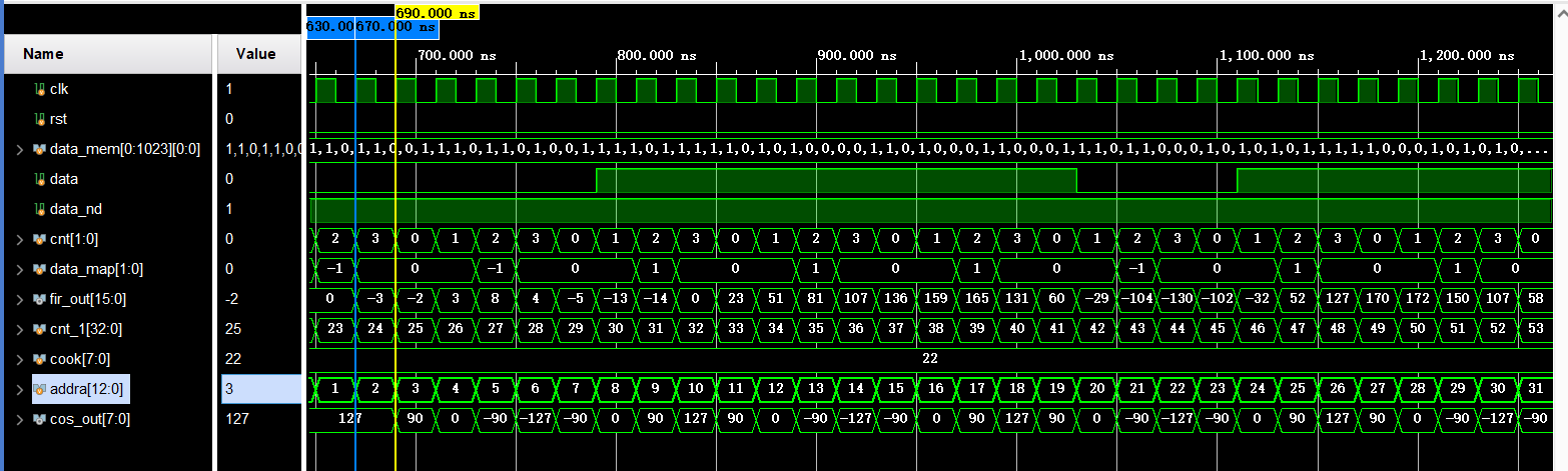
-
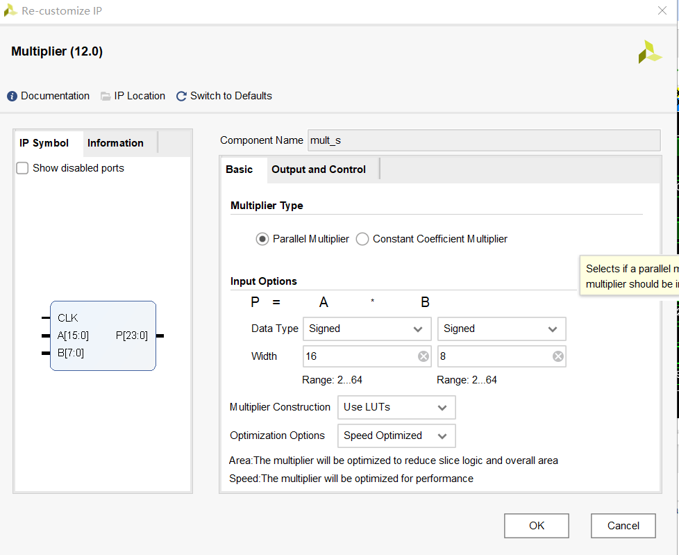
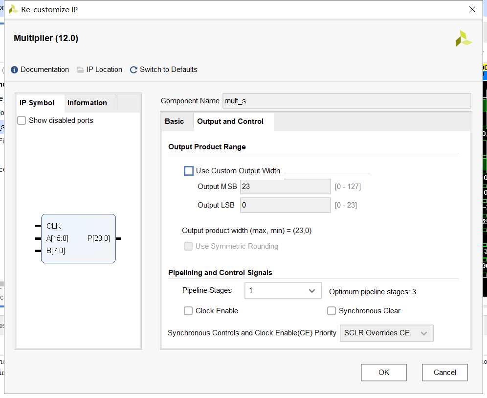
乘法器实现上变频
-
MATLAB
1
s_up = data_bx .* cos_bit;
-
Verilog
Design
1
2
3
4
5
6
7
8
//乘法器
//wire [23:0] s_up;
mult_s mult_s_m (
.CLK(clk), // input wire CLK
.A(fir_out), // input wire [15 : 0] A
.B(cos_out), // input wire [7 : 0] B
.P(s_up) // output wire [23 : 0] P
);IP核设置
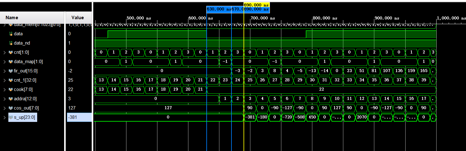
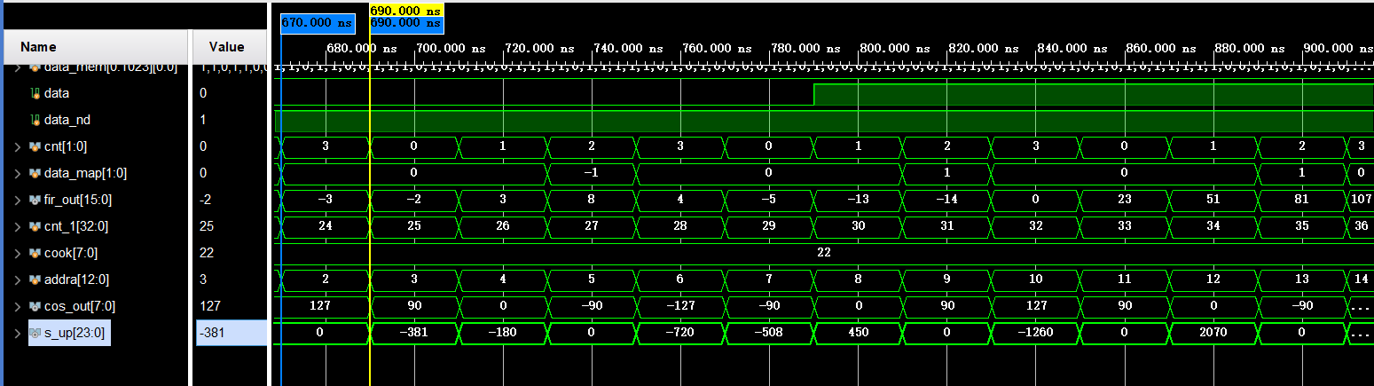
-
仿真输出
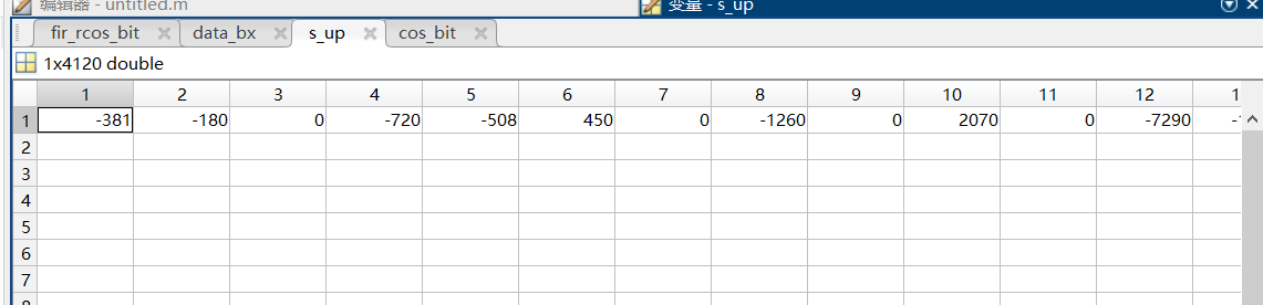
结果验证
首先需要在vivado中输出txt文件
- MATLAB
1
2
3
data_out = importdata("test.txt");
y = s_up - data_out';
plot(y);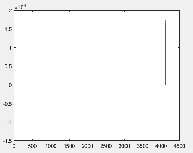
这张图出现的原因是输入数据为1024,4倍上采样之后为4096个点,理论上通过滤波器之后应该是4096个点,但MATLAB中卷积之后为4120个点,滤波器两边的拖尾造成
- Verilog
1
2
3
4
5
6
7
8
9
10
11
12
13
14
15
16
17
18
19
20
21
22
23
24
reg [14:0] counter_1;
reg [32:0] cnt_1 = 33'd0;
always @(posedge clk) begin
if (rst) begin
counter_1 <= 15'd0;
end
else if (cnt_1 == 33'd4160) begin
$fclose(save_file);
end
else begin
// $fdisplay(save_file,"%d",$signed(s_up));
$fwrite(save_file,"%d\n",$signed(s_up));
end
end
//用于观察的计数器
always @(posedge clk) begin
if(rst)begin
cnt_1 <= 33'd0;
end
else begin
cnt_1 <= cnt_1 + 33'd1;
end
end
附录
MATLAB
1 | clc;clear;close all; |
Verilog
Design
1 | module bpsk_send( |
Testbench
1 |
|
代码优化及思考
目录
MATLAB代码基本不变,主要是verilog代码
(直接数据输入,上采样环节在IP核中设置)
HDL
1 | reg [1:0] data_map = 2'b00; //映射之后的序列 |
映射序列的写法
1 | wire [1:0] data_map ; |
-
结果输出
IP核设置(FIR)
-
内插倍数设置为4
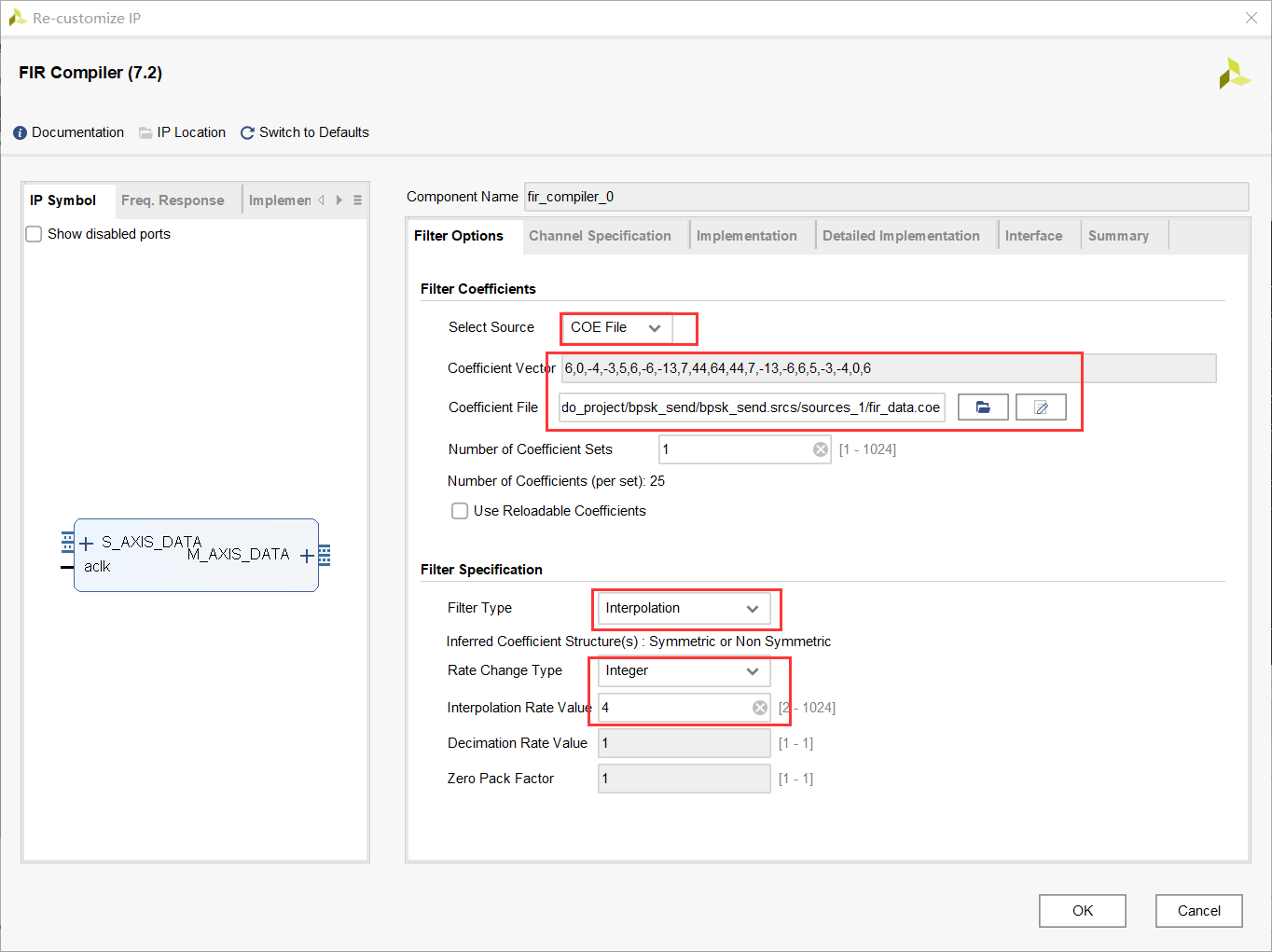
-
输出结果 (错误→正确)
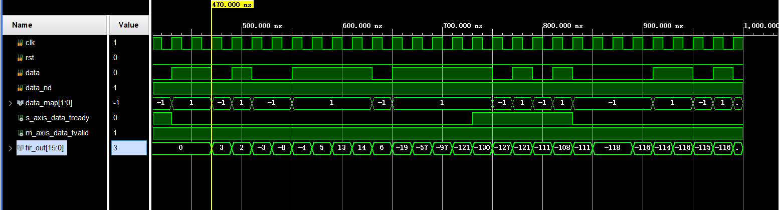
⁉️输出序列是错的
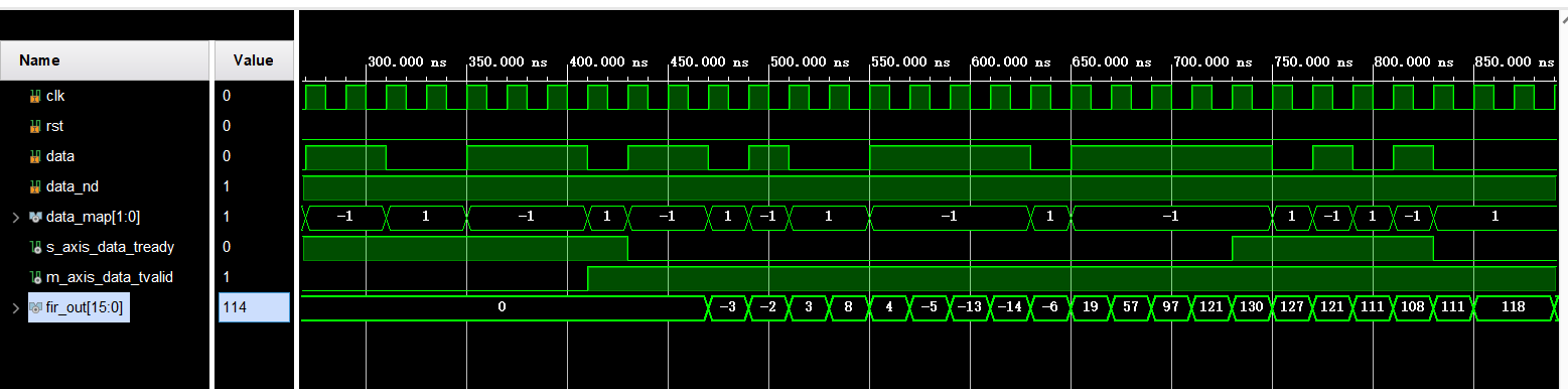
🚗找了好久,序列的前三个数与MATLAB数据就差个负号,以为是映射方式错了,改了半天,原来是使能信号,修改如下;1
2
3
4
5
6
7
8
9fir_compiler_0 fir_compiler (
.aclk(clk), // input wire aclk
.s_axis_data_tvalid(data_nd), // input wire s_axis_data_tvalid
.s_axis_data_tready(s_axis_data_tready), // output wire s_axis_data_tready
.s_axis_data_tdata({6'd0,data_map}), // input wire [7 : 0] s_axis_data_tdata
.m_axis_data_tvalid(m_axis_data_tvalid), // output wire m_axis_data_tvalid
.m_axis_data_tdata(fir_out) // output wire [15 : 0] m_axis_data_tdata
);
代码附录
1 | module bpsk_send( |
testbench
1 | module tb_bpsk_send( |
代码学习
读写txt文件
1 | //testbench |